
Power cable insulation resistance is one of the most intuitive indicators to judge the health status of cable insulation. It reflects whether the insulating layer can effectively isolate the charged conductor from the ground or other phases. Whether for factory delivery inspection, newly laid cable acceptance, or regular maintenance of cables that have been running for years, insulation resistance testing is an essential routine item. Even if the cable can be energized temporarily, hidden defects such as dampness, insulation scratches and aging will gradually reduce insulation resistance and finally trigger ground fault or short‑circuit accident.
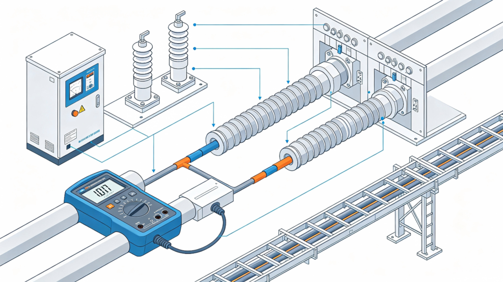
Understanding Cable Insulation Resistance
Insulation resistance refers to the resistance formed by the cable insulating medium between conductor and sheath, or between different core conductors under DC voltage. Unlike conductor resistance which pursues low value, qualified cable insulation needs extremely high resistance.
Many purchasers and construction teams confuse insulation resistance with conductor DC resistance. Conductor resistance checks whether the copper or aluminum core meets the cross‑section requirement, while insulation resistance checks the integrity of non‑conductive insulation materials. The two parameters are independent and cannot replace each other.
XLPE, PVC and EPR are common insulation materials, and their insulation performance varies greatly under different temperature and humidity. High temperature and humid environment will make the measured insulation resistance drop obviously, which is a normal physical characteristic rather than direct proof of cable quality problems.
Standard Test Method for Cable Insulation Resistance
The most widely adopted method on site is using a megohmmeter (megger). The test principle is to apply specified DC high voltage to the cable and read the insulation resistance value.
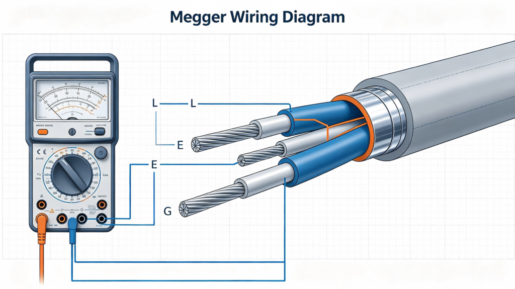
Select proper megger voltage
Voltage selection shall match the rated voltage of the tested cable. Too low test voltage cannot expose tiny insulation defects; excessively high voltage may damage intact insulation.
- Low‑voltage cable (0.6/1kV): 500V or 1000V megger
- Medium‑voltage cable (3.6/6kV ~ 18/30kV): 2500V megger
- High‑voltage cable above 35kV: 5000V megger
Pre‑test preparation
- Fully disconnect the cable from all power supplies, switchgears and loads. Confirm zero voltage by live‑line detector.
- Disconnect both ends of the cable from terminal accessories. Keep the ends dry and clean, avoid surface leakage caused by dust or moisture.
- Discharge the cable sufficiently before and after testing. Residual charge inside long cables may cause electric shock and distort test data.
- Record ambient temperature and relative humidity for later data correction.
Test steps
- Connect megger terminals: Line (L) to cable conductor, Earth (E) to cable metal sheath, Guard (G) to insulation surface if surface leakage interference is severe.
- Start the megger steadily and keep rated test voltage. Record reading at 60 seconds (R60s).
- For high‑quality medium‑voltage cables, record R15s and R60s to calculate polarization index PI = R60s/R15s.
- After reading, stop the instrument and discharge the cable core completely.
Callout: Never touch cable terminals during testing. Long‑length power cables can store huge electric charge even after the megger stops working.
Reference Standard Values of Insulation Resistance
There is no fixed universal constant value for all cables. Insulation resistance decreases as cable length increases and temperature rises. The industry usually evaluates by insulation resistance per kilometer at 20℃.
For reference:
- 0.6/1kV XLPE power cable: ≥100 MΩ·km
- 8.7/10kV XLPE cable: ≥1000 MΩ·km
- 18/30kV XLPE cable: ≥2000 MΩ·km
PVC insulated cables generally have lower insulation resistance than XLPE under the same conditions. If the measured value is far below the reference range, or the three‑phase values show obvious unbalance, further inspection is required.
Note: Field measured data must be converted to 20℃ equivalent value. Testing in rainy days or high humidity often leads to false low readings.
Common Causes of Low Insulation Resistance
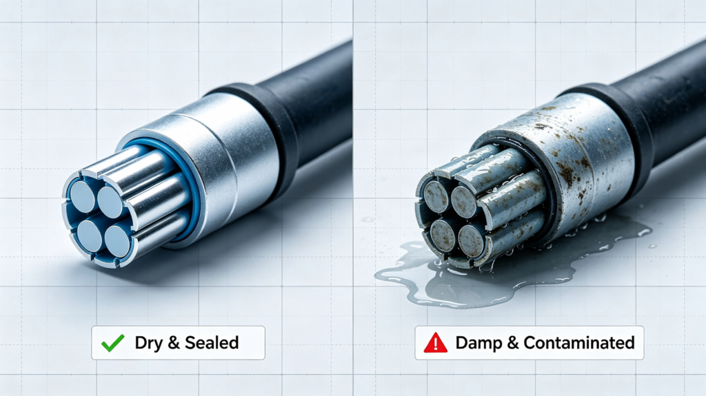
Cable end damp or contaminated
This is the most frequent cause on construction sites. Cable ends are not sealed tightly during transportation and laying. Rainwater, underground water or humid air penetrates into the core. Dust, conductive mud and cutting residues attached to insulation surfaces also form leakage paths.
Mechanical damage during cable pulling or bending
Over‑large pulling tension, bending beyond minimum bend radius, sharp rock extrusion and nail piercing will produce tiny cracks or notches inside insulation. These invisible damages may not break down immediately, but gradually absorb moisture and pull insulation resistance down. You can link to our article about [cable pulling tension standard] and [cable bending radius standard] to avoid installation damage.
Insulation aging after long‑term operation
Long‑term thermal aging caused by overload operation, repeated thermal cycling, chemical corrosion from soil or sewage will degrade insulation molecular structure. Insulation resistance declines slowly year by year. Check our article about [cable overload operation risks] for overload prevention.
Defects of cable termination or joint
Poor sealing of heat shrink / cold shrink terminals, improper stripping and scratches on main insulation during joint making are typical weak points. Even if the cable body is good, the termination section will cause the whole‑cable insulation test failure.
Troubleshooting Steps for Low Insulation Resistance
- Retest after cleaning and drying cable ends. Use hot air blower to dry the terminal surface and test again. If the value recovers, the problem is only surface moisture.
- Separate cable sections. Test each segment section by section to locate which segment has low resistance.
- Check terminations and intermediate joints first. Re‑make defective cable terminals if needed.
- If the cable body shows continuous low insulation resistance and cannot be dried out, the cable insulation may have internal water tree or mechanical damage. Do not put it into operation blindly.
- For important projects, arrange high‑voltage withstand test or partial discharge detection for further confirmation.
Best Practices to Maintain High Insulation Resistance
- Keep cable sealed all the time during storage, transportation and laying. Use waterproof end caps for cut ends.
- Avoid dragging cables directly on sharp rock, concrete edges or metal scraps.
- Control cable load strictly to prevent long‑time overheating acceleration of aging.
- Schedule periodic insulation resistance tests for underground cables and cables in humid tunnels, especially before rainy seasons.
- Select suitable cable sheath material according to environment: anti‑corrosion sheath for chemical‑polluted soil, water‑blocking structure for high groundwater area.
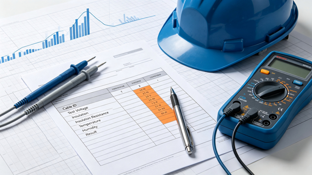
FAQ About cable insulation resistance
A: Not recommended. Low insulation resistance represents higher risk of earth fault. Temporary power‑on may cause breakdown, equipment damage and safety accidents. You need to find the root cause and fix it first.
A: PI = insulation resistance at 60s divided by reading at 15s. It helps judge insulation aging status for medium and high voltage cables. Healthy insulation usually has PI above 1.5.
A: Insulating medium becomes more conductive at higher temperature. It is a normal physical property. That is why test results need temperature correction.
Conclusion
Insulation resistance test is simple, low‑cost and highly effective for cable health diagnosis. Mastering correct megger operation, understanding reference values and recognizing common fault sources can help your engineering team avoid hidden cable faults before commissioning. Regular testing and standardized construction together extend cable service life and reduce unexpected power outages.
If you need reliable XLPE power cables with stable insulation performance for your industrial, renewable energy or infrastructure projects, feel free to contact our team for detailed product specifications and technical support.